Block Diagram: Multiple Door Access System
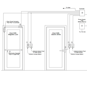
Block Diagram for Multiple Door Controller Access Systems
- An access device such as a keypad, card reader, or fingerprint reader, or combination of these devices is located outside the entry point. The entry point can be a gate, interior, or exterior door.
- A pushbutton or push-rail is located on or adjacent to the door for egress. All doors must have a positive fail-safe way of exiting.
- A magnetic lock or electric strike is used to physically secure the door.
- Power supply with battery backup is used to power the keypad, locking device, and the controllers. The battery backup is necessary to assure that access is available during power outages.
- Each controller can have 1-4 doors connected to it. The controller on most installations is configured from 2-4 doors. When control over one door is needed a stand alone system is usually utilized. Most controllers can be connected directly to a printer and or a computer to view transactions. User info is entered into controller that determines which doors or gates, and what times and days the user can have access.